
The construction design is very simple and based around the micro USB PCB I've got off eBay for like $0.75 a pair. It went out very nicely overall and works flawlessly. Goodbye "pill" batteries.

The PCB fits the stock rear end cap diameter very well. The port location on the side is most optimal, as the power cable comes from the 5V USB powerbank magnet-mounted on the side of my Z12 OTA. 5V is just 0.5V higher than the battery provided voltage, so there is no any issues with that to power the laser pump.
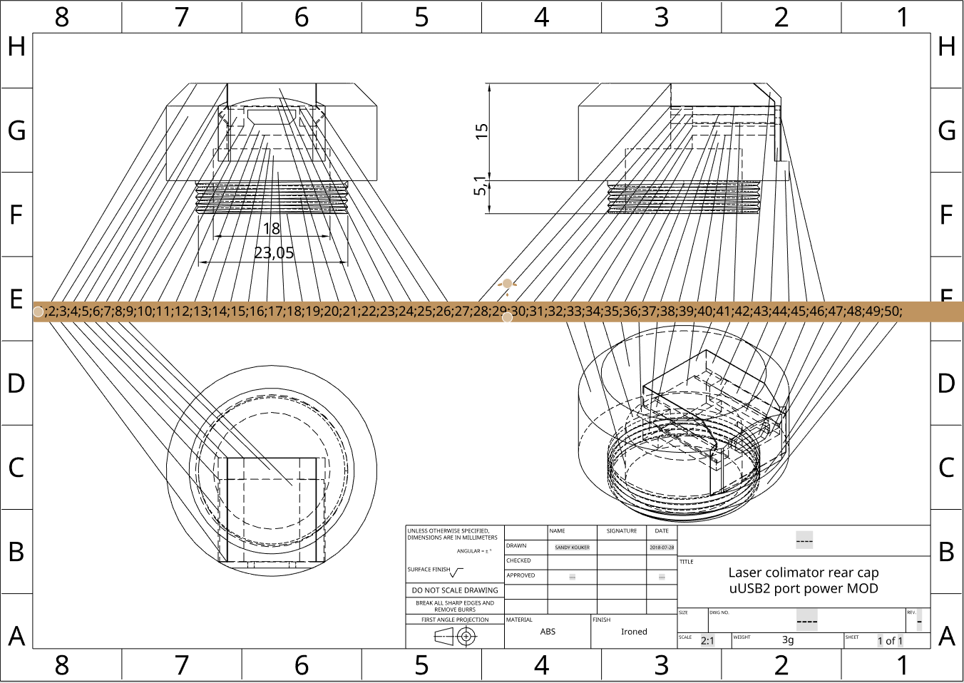
Construction details
- The PCB mounted in the well covered by the sliding from the side lid (over triangular rails) with the USB port inlet. So the construction can be disassembled if necessary. Though it's a tight fit and required a bit of sanding.
- The threaded end has been made with beveled end-ramp which allows to screw it into the collimator body with some force at the end to make (self)unscrewing tougher.
- The central well for wires is wide enough to accommodate 4-pin male connector, though I've ended up with just soldering two wires to save the space.
- The wires contacting the laser sping (-) and body (+) are ordinary sleaved single strand copper wires (~24ga). Pre-bending them to fit in and over is sufficient to make reliable contact from the first attempt (don't forget that the spring of the pen laser is Negative polarity! (contrary to ordinary flashlights).
- USB connector side made flat with a notch from below to help finding it by touch blindly.
Drafts
I may go over this numbers list above one day and explain the design in details. Though a set of images would suffice for now:
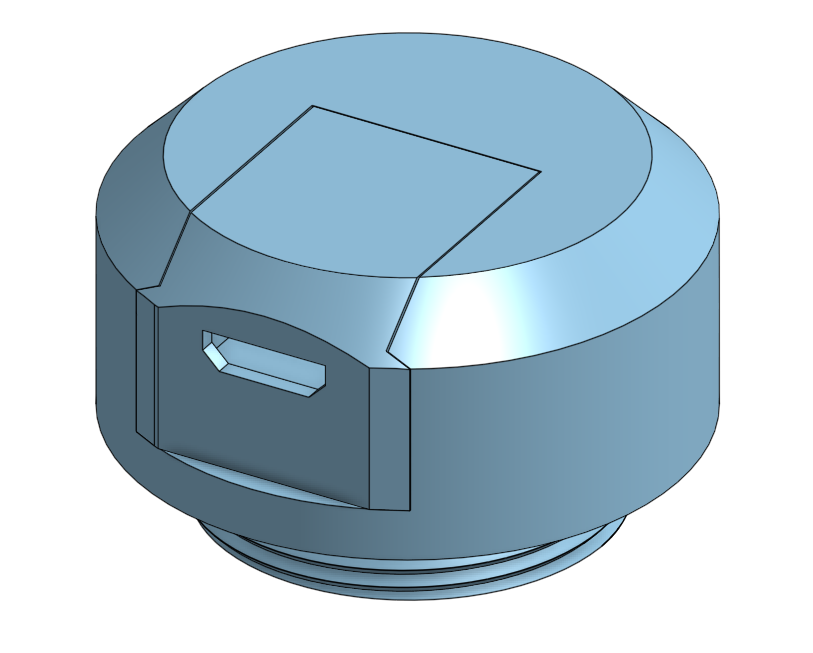
Assembled tail cap. Note the notch under the port. Good tactile reference even when working in gloves.
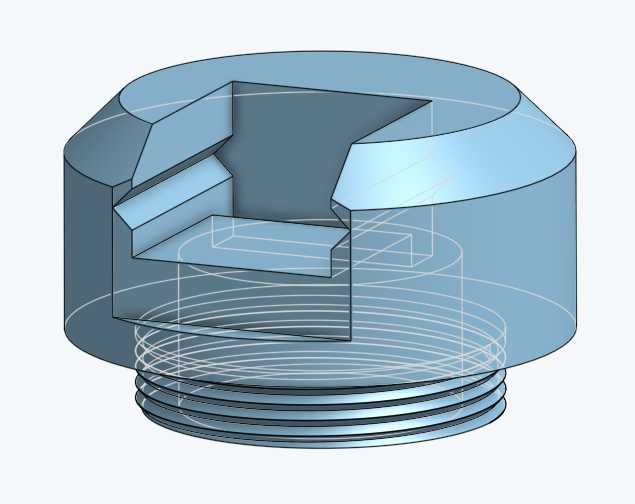
With the PCB "Drawer" (below) out.

The PCB "Drawer" (upside down). Flat bars on the sides of the port opening are pressing against the PCB snuggly holding it in place (when sanding - add a tiny slope outwards making the wedge.
Files
Thingiverse: https://www.thingiverse.com/thing:3036490
No comments:
Post a Comment